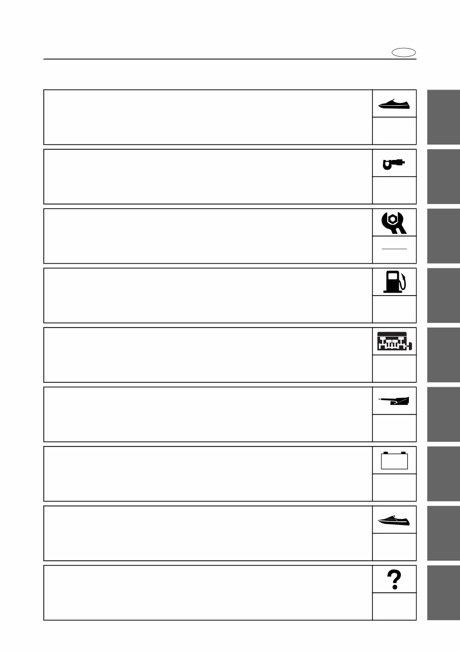
E Contents General information GEN INFO Specification SPEC Periodic check and adjustment CHK ADJ Fuel system FUEL Power unit POWR Jet pump unit JET PUMP Electrical system ELEC Hull and hood HULL HOOD Troubleshooting TRBL SHTG – + 1 2 3 4 5 6 7 8 9
E GEN INFO 2 3 4 5 6 7 8 9 Chapter 1 General information How to use this manual ................................................................................. 1-1 Manual format ............................................................................................ 1-1 Symbols ..................................................................................................... 1-2 Abbreviation............................................................................................... 1-3 Safety while working...................................................................................... 1-4 Fire prevention........................................................................................... 1-4 Ventilation .................................................................................................. 1-4 Self-protection ........................................................................................... 1-4 Parts, lubricants, and sealants .................................................................. 1-4 Good working practices ............................................................................. 1-5 Disassembly and assembly ....................................................................... 1-5 Identification number..................................................................................... 1-6 Primary I.D. number .................................................................................. 1-6 Engine serial number ................................................................................. 1-6 Jet pump unit serial number ...................................................................... 1-6 Hull identification number (H.I.N.) .............................................................. 1-6 Special service tool ....................................................................................... 1-7 Measuring .................................................................................................. 1-7 Removal and installation ........................................................................... 1-9 Feature and benefit ...................................................................................... 1-14 Watercraft overview ................................................................................. 1-14 Rear seat ................................................................................................. 1-15 Telescopic steering system ..................................................................... 1-16 Shift lever assembly ................................................................................ 1-17 Watertight compartment .......................................................................... 1-18 Fire extinguisher location......................................................................... 1-18 Hull design ............................................................................................... 1-19 Engine overview ...................................................................................... 1-20 Supercharger assembly........................................................................... 1-21 Air cooler assembly ................................................................................. 1-21 ECM......................................................................................................... 1-22 Drive shaft ............................................................................................... 1-22 Dual analog meter unit ............................................................................ 1-23 Information display warnings ................................................................... 1-24 Self-diagnosis .......................................................................................... 1-24 Yamaha Security System ........................................................................ 1-25
E GEN INFO 1 2 3 4 5 6 7 8 9 Technical tips ............................................................................................... 1-26 Engine control .......................................................................................... 1-26 ECM circuit diagram.......................................................................... 1-27 ECM coupler layout ........................................................................... 1-28 Control system......................................................................................... 1-30
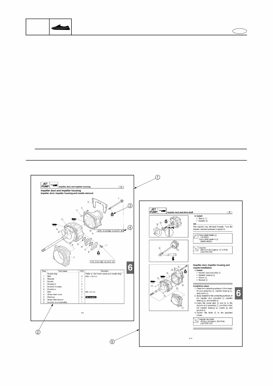
1-1 E GEN INFO 2 3 4 5 6 7 8 9 How to use this manual Manual format The format of this manual has been designed to make service procedures clear and easy to under- stand. Use the information below as a guide for effective and quality service. • Parts are shown and detailed in an exploded diagram and are listed in the component list (refer to 1 in the figure below for an example page). • The component list consists of part names and quantities (refer to 2 in the figure below). To assemble or install the components, reverse the steps indicated in the component list. • Symbols are used to indicate important aspects of a procedure, such as the grade of lubricant and lubrication point (refer to 3 in the figure below). • Tightening torque specifications are provided in the exploded diagrams (refer to 4 in the figure below for an example), and in the related detailed instructions. Some torque specifications are listed in stages as torque figures or angles in degrees. • Separate procedures and illustrations are used to explain the details of removal, checking, and installation where necessary (refer to 5 in the figure below for an example page). TIP For troubleshooting procedures, refer to “Troubleshooting” in Chapter 9. How to use this manual
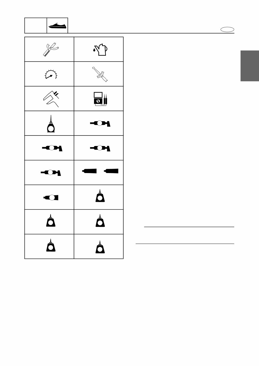
1-2 E GEN INFO 1 2 3 4 5 6 7 8 9 Symbols Symbols 1 to 6 indicate specific data. 1 Special service tool 2 Specified oil or fluid 3 Specified engine speed 4 Specified tightening torque 5 Specified measurement 6 Specified electrical value (resistance, voltage, electric current) Symbols 7 to A in an exploded diagram indi- cate the grade of lubricant and the lubrication point. 7 Apply 4-stroke motor oil 8 Apply water resistant grease (Yamaha grease A) 9 Apply molybdenum disulfide grease 0 Apply Epnoc grease AP #0 A Apply Silicone grease Symbols B to H in an exploded diagram indi- cate the type of sealant or locking agent and the application point. B Apply ThreeBond 1194E or ThreeBond 1280B C Apply Gasket Maker D Apply LOCTITE 271 (red) E Apply LOCTITE 242 (blue) F Apply LOCTITE 572 G Apply LOCTITE 648 H Apply silicone sealant TIP Additional symbols may be used in this man- ual. 1 2 3 4 5 6 7 8 9 0 A B C D E F G H T R . . E A M EP SG 1280B 1194E GM 271 LT 242 LT 572 LT 648 LT SS How to use this manual
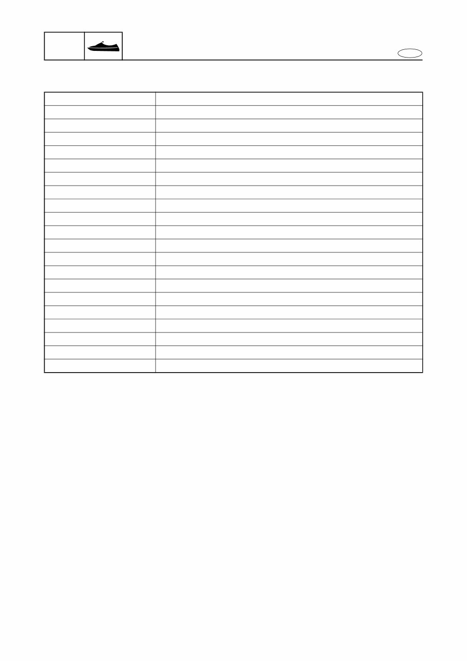
1-3 E GEN INFO 2 3 4 5 6 7 8 9 Abbreviation The following abbreviations are used in this service manual. Abbreviation Description API American Petroleum Institute APS Accelerator position sensor BOW Bow end ECM Electronic Control Module ETV Electronic throttle valve EX Exhaust IN Intake OL Overload OTS Off-throttle steering system PORT Port side QSTS Quick Shift Trim System RPM Revolutions Per Minute SAE Society of Automotive Engineers STBD Starboard side STERN Stern end TCI Transistor Controlled Ignition TDC Top Dead Center TPS Throttle Position Sensor UP Upside YDIS Yamaha Diagnostic System How to use this manual
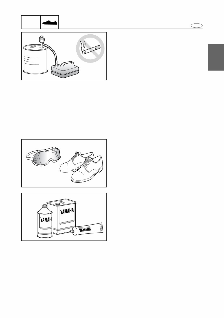
1-4 E GEN INFO 1 2 3 4 5 6 7 8 9 Safety while working To prevent and accident or injury and to ensure quality service, follow the safety proce- dures provided below. Fire prevention Gasoline is highly flammable. Keep gasoline and all flammable products away from heat, sparks, and open flames. Ventilation Gasoline vapor and exhaust gas are heavier than air and extremely poisonous. If inhaled in large quantities, they may cause loss of con- sciousness and death within a short time. When test running an engine indoors (e.g., in a water tank), make sure to do so where ade- quate ventilation can be maintained. Self-protection Protect your eyes by wearing safety glasses or safety goggles during all operation involving drilling and grinding, or when using an air com- pressor. Protect your hands and feet by wearing protec- tive gloves and safety shoes when necessary. Parts, lubricants, and sealants Use only genuine Yamaha parts, lubricants, and sealants, or those recommended by Yamaha, when servicing or repairing the watercraft. Under normal conditions, the lubricants men- tioned in this manual should not harm or be hazardous to your skin. However, you should follow these precautions to minimize any risk when working with lubricants. 1. Avoid contact with skin. Do not, for exam- ple, place a soiled rag in your pocket. 2. Wash hands and any other part of the body thoroughly with soap and hot water after contact with a lubricant or lubricant soiled clothing has been made. 3. Change and wash clothing as soon as possible if soiled with lubricants. 4. To protect your skin, apply a protective cream to your hands before working on the watercraft. Safety while working
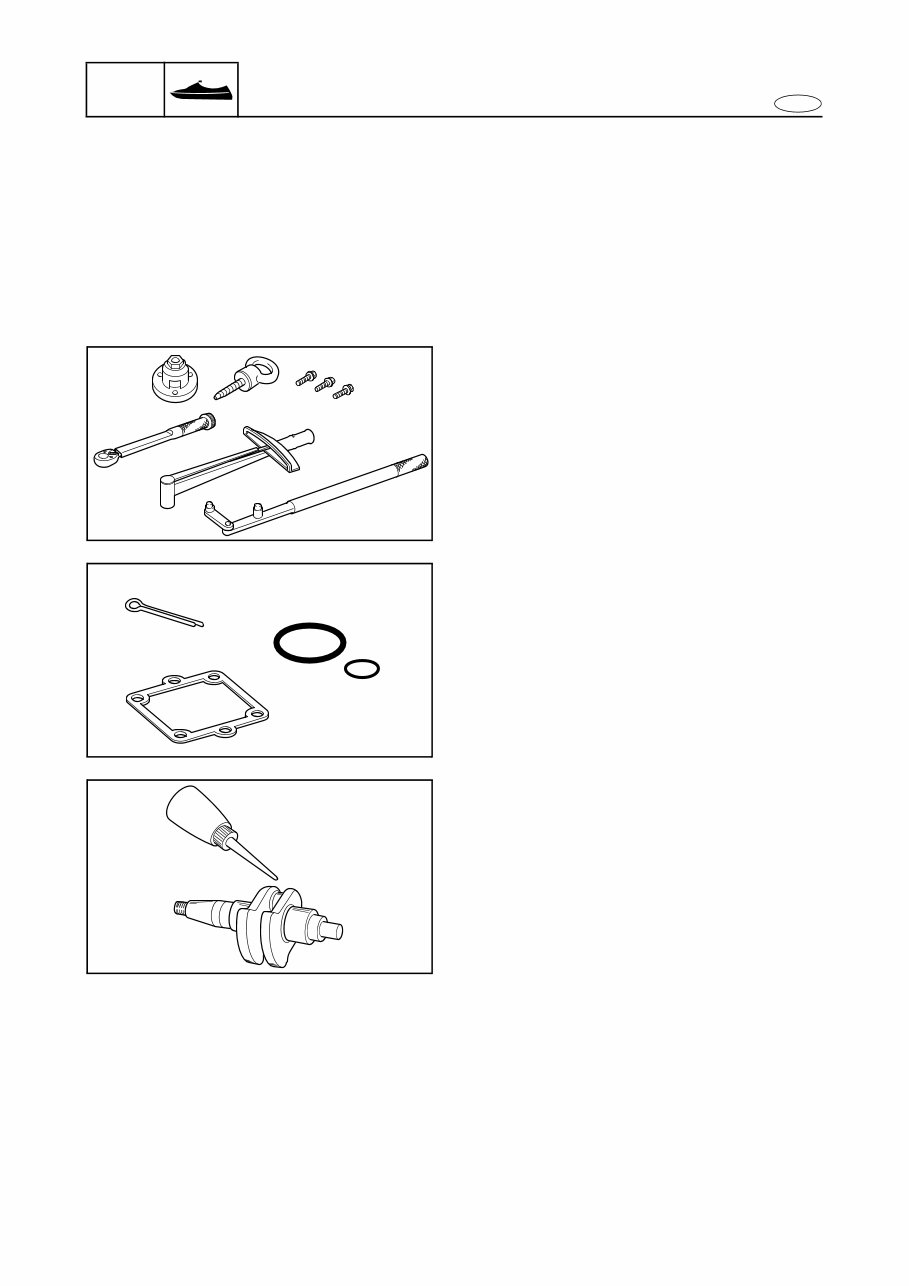
1-5 E GEN INFO 2 3 4 5 6 7 8 9 5. Keep a supply of clean, lint-free cloths for wiping up spills, others. 6. Maintain good standards of personal and industrial hygiene. Good working practices Special service tool Use the recommended special service tools to protect parts from damage. Use the right tool in the right manner; do not improvise. Tightening torques Follow the tightening torque specifications pro- vided throughout the manual. When tightening nuts, bolts, and screws, tighten the large sizes first, and tighten fasteners starting in the cen- ter and moving outward. Non-reusable parts Always use new gaskets, seals, O-rings, cotter pins, others, when installing or assembling parts. Disassembly and assembly 1. Use compressed air to remove dust and dirt during disassembly. 2. Apply oil or fluid to the contact surfaces of moving parts before assembly. 3. Install bearings with the manufacture iden- tification mark in the direction indicated in the installation procedure. In addition, make sure to lubricate the bearings liber- ally. 4. Apply a thin coat of water resistant grease to the lip and periphery of an oil seal before installation. 5. Check that moving parts operate normally after assembly. Safety while working
This manual provides procedures for disassembly and reassembly, inspection, maintenance, component identification, and unit repair, along with service specifications for the Yamaha WaveRunner FZR / GX1800, and FZS / GX1800A Personal Watercraft.
It is suitable for both first-time do-it-yourselfers and professional mechanics. Detailed drawings and clear photographs provide all the necessary information to perform the work accurately. Troubleshooting, tune-up, maintenance, and repair become manageable when the proper tools, equipment, and procedures are known.
Models Covers:
Yamaha WaveRunner FZR - GX1800 (F2R)
Yamaha WaveRunner FZS - GX1800A (F2C)
Manual Contents:
General information
Specification
Periodic check and adjustment
Fuel system
Power unit
Jet pump unit
Electrical system
Hull and hood
Troubleshooting
Wiring Diagram
Language: English
Requirements: Reader
Total pages: 400+
This manual is in Adobe format, making it extremely portable and easy to navigate from one computer to another. It allows for convenient browsing, printing of specific pages, or the entire manual. Many mechanics prefer electronic manuals for easy access during maintenance, using a laptop or printed pages as needed.
Most service manual chapters start with an assembly or system illustration, diagrams, exploded parts view, pictures, service information, and troubleshooting for the section. Subsequent pages provide detailed procedures. If the source of the trouble is unknown, the troubleshooting page provides a list of causes and effects to determine the problem.
This backup manual is intended for individuals who already own a paper copy of the manual. It is designed to protect the original manual from dirt, grime, and damage, ensuring its cleanliness and safety.