Onan NHE, NHEL Series Service Manual Cummins Onan Generator Repair Book 940-0502
What's Included?
Lifetime Access
Fast Download Speeds
Online & Offline Access
Access PDF Contents & Bookmarks
Full Search Facility
Print one or all pages of your manual
RV Electric Generating Set (Spec A-C) Service Manual GenSets 940-0502 7-87 Printed In U.S.A.
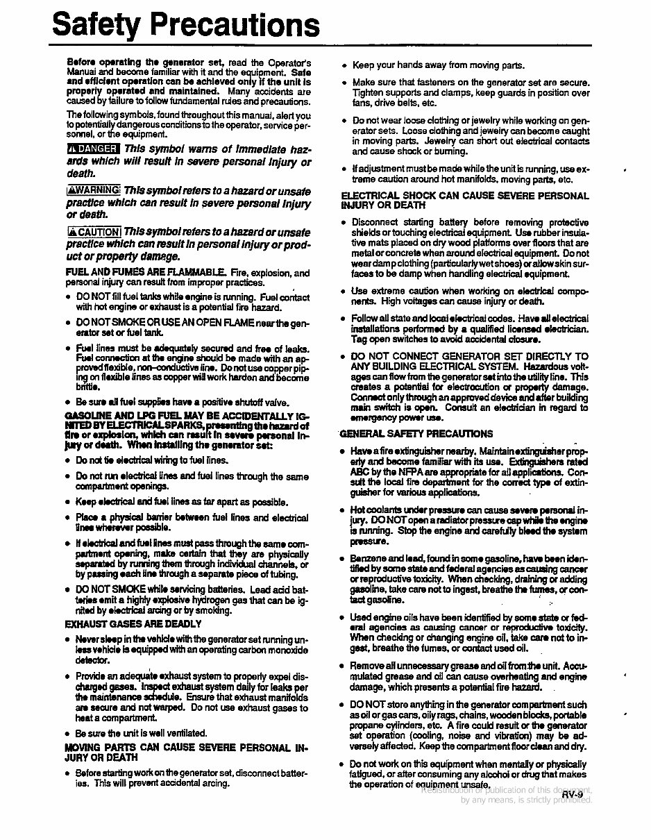
Safety Precautions Boforo oparatlng tho generator set, read the Operator's Manual and become familiar with it and the ui ment. Safe and rffldent oporation can ba achleved oqy 1 the unit Is pmpeq oporatod and maintained. Many accidents are caused y failure to follow fundamental rdes and precautions. The followingsymbols, foundthroughoutthis manual, alert you to potentiall dangerousconditionsto theqmator,service per- sonnel, or x e equipment. 77th sjmboi warns of immediate haz- ards which will result In sevete personal I n j q or death. iMWAANlNGI~fssym~lrefers to a hazard orunsafe practrce which can result in severe personal Injuty or death. IricAunoNj Thlssymbolrefers to a hazard or unsafe practice whlcb can msult in personal fnjuty orpmd- uct or propew d8mge. FUEL AND FUMES ARE FLAMMABLE. Fire. explosion, and personal injury can result from improper practices. DO NOT fill fuel tanks while engine is running. Fuel cork~ct with hot engine or exhaust is a potential fire hazard. DO NOTSMOKE OR USEAN OPEN FLAMEnearthegen- erator set or fuel tank hnl lines must be dquatrly secund and free of leaks. Fuolconnoction at tlw eMne should be made with an ap- prowdllexjble,~uCtiveline. Donotusecopperpip- iq on floxible lines as copper will work harden and become bnttlr. Bo sure dl fuel supplh haw a positivo shutoff valve. -LINE AND LPG FUEL MAY BE ACClDEMALLY IG NlED BY UECTRICALSPARKS, rwmtfngthr hazud of fin or oxp~on, w~ch an muR In mvw. pmona, In- luy M duth. Whm lnthlllng tho genorator Mt: Do not tk electrical wiring to fuel lines. Do not M electrid lines and fuel lines through the same mpartmont openings. Koep rkctrical and fuel lines as far apart as possible. Phco a physical bonier botwaen fuel lines and elsctn'cal Pnawinmfer possible. ll okchical and furl fines mud pass through the mo com- pubnont qning, make certain that they are physically sqamtod by rumingthem through indii channels, or by pusing oach lino through a separate piece of tubing. DO NOT SMOKE while soruicing batteries. Lead aad bat- t.ri.s omit a highly oxplaSiv6 hyiimgen gas that can be g- dod by okctrical arcing or by smoking. EXHAUST GASES ARE DEADLY Now sloop in the vshido with the generator set Nnning un- kvohide is equipped with an operating carbon monoxide dasctor. e Provide an adeqde exhaust system to properly expel dis- charged gases. In exhaust system daily for leaks per am securo and not warped. Do mi use exhaust gases to heat a compartment. e Be sure the unit is well ventilated. JURY OR DEATH e Before startingwork on the generator set, disconnect batter- th, maintenance Jz de. Ensure that exhaust manifolds MOVING PARTS CAN CAUSE SEVERE PERSONAL IN- ies. This will prevent acadental arcing. 0 Keep your hands away from moving parts. 0 Make sure that fasteners on the generator set are secure. Tighten supports and clamps. keep guards in position over fans, drive belts, etc. 0 Do not wear loose clothing or jewelry while working on gen- erator sets. Loose clothing andjewelry can become caught in moving parts. Jewelry can short out electrical contacts and cause shock or burning. e If adjustmentmustbemadewhilethe unit is running, use ex- treme caution around hot manifolds, moving parts, etc. ELECTRICAL SHOCK CAN CAUSE SEVERE PERSONAL INJURY OR DEATH , Disconnect starb'ng battery before removing protective shields or touching electrical equipment Use rubber insula- tive mats placed on dry woad platformsover floors that are metal or concretewhen around electrical equipment. Do not wear dampclothing (particu1arlywetshoes)orallowskinsur- faces to be damp when handling electrid equipment. Use extreme caution when working on electrical compo- nents. High voltages can cause injury or death. Follow all state and local ekctricald e s . Havo dl electrical installations perform4 by a qualied licensed electrician. Tag open switches to avoid accidental closure. DO NOT CONNECT GENERATOR SET DIRECTLY TO agescanflowfrom thegeneratorsotintotheutilityline. This creates a potential for electrocution oc pmporty damage. Con& only through an apprwed device and after building nuin switch is 0p.n. Consult an electriaan m regard to -rgsncyponnr-. ANY BUILDING ELECTRICAL SYSTEM. Hazard- vdt- 'GENERAL SAFl3Y PRECAUTDNS ~ave afire oxtinguisimr new. ~aintainoxtinguistmr prOp edy and become familiar with its use. Extbrguishers rated ABC by the NFPA are appropriatefor allappliations. Con- sdt the Id fire department for the correct type of extin- guisher for various applications. Hot coolants under prossure can cause sovom porsolwl in- juty. DONOTo~aradiatorpre~ruecepwtriktheengine is running. Stop the engine and carefdly bbd th. systom pnsue. Benzene and bad, found in m ogasoline, haw boon idon- Wkdbysane~eandf~eralagenciesas~ng~r or reproduCtive toxicity. When checking, draining or adding gasoline, take care not to ingest, breathe tha fumes, or con- tact gasdine. Used engine oils have been identified by 801110 st& or fad- ed agencies as causing cancer or reproductivb toxicity. When checkjng or changing engine oil, take cam not to in- gest. breathe the fumes, or contact used oil. Remove all unnecessary grease and oil from.th. unit. Accu- mulated grease and oil can cause overheating and engine damage, which presentsa potential fire hazard. DO NOTstore anything in the generator compartment such as oil or gas cans, oily rags, chains, wooden blocks, portable propane cylinders, etc. A fire could result or tho generator set operation (cooling, noise and vibration) may be ad- versely affected. Keepthecompartment floor doan and dry. Do not work on this equipment when mentaliy or physically fatigued. or after consuming any alcohol or drug that makes the operation of equipment unsafe. I 1. RV-9
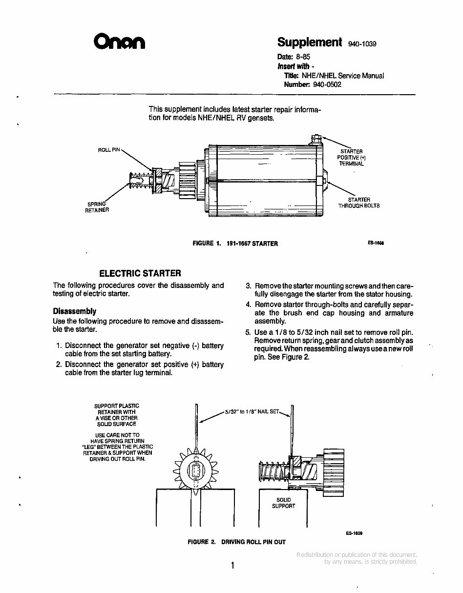
Supplement 940-1039 Date: 8-85 Insert with - T i NHE/NHEL Service Manual Number: 940-0502 . This supplement includes latest starter repair informa- tion for models NHE/NHEL RV gensets. FIGURE 1. 191-1667 STARTER =16M ELECTRIC STARTER The following procedures cover the disassembly and testing of electric starter. Disassembly Use the following procedure to remove and disassem- ble the starter. 1. Disconnect the generator set negative (-) battery 2. Disconnect the generator set positive (+) battery cable from the set starting battery. cable from the starter lug terminal. SUPPORT PLASTIC RETAINER WITH A VISE OR OTHER SOUD SURFACE USE CARE NOT TO HAVE SPRING RETURN ~ _ _ ~ RETAINER & SUPPORT WHEN DRIVING OUT ROLL PIN. 3. Removethe starter mounting screws and then care- fully disengage the starter from the stator housing. 4. Remove starter through-bolts and carefully separ- ate the brush end cap housing and armature assembly. 5. Use a 1 /8 to 5/32 inch nail set to remove roll pin. Remove return spring, gear and clutch assembly as required. When reassembling always usea new roll pin. See Figure 2. n 5/32" lo 118 NAIL S E T , "LEG" BETWEEN THE PLASTIC SOLID SUPPORT FIGURE 2. DRIVING ROLL PIN OUT 1
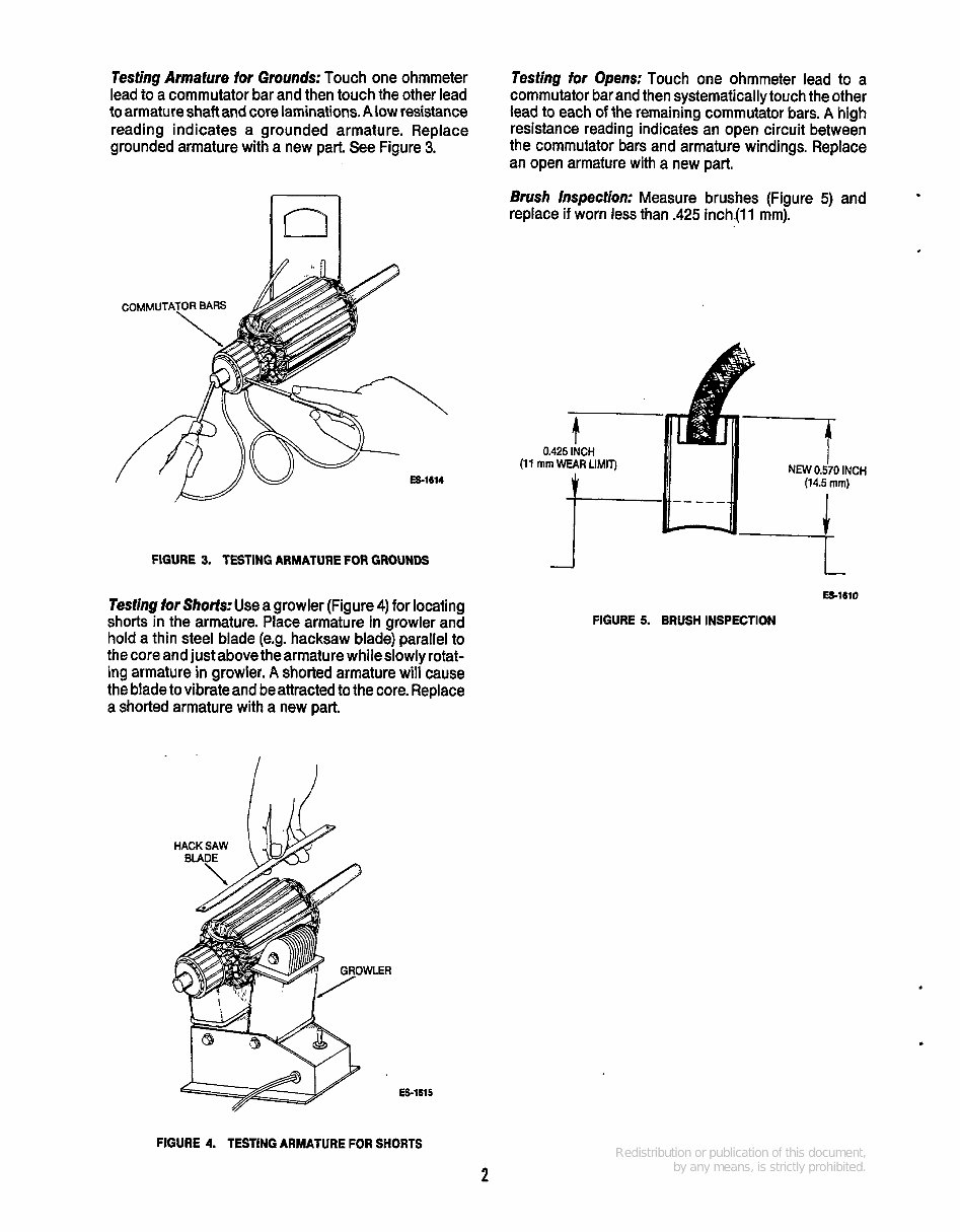
Testing Armature lor Grounds: Touch one ohmmeter lead to a commutator bar and then touch the other lead to armature shaft and core laminations. Alow resistance reading indicates a grounded armature. Replace grounded armature with a new part. See Figure 3. Testing for Opens: Touch one ohmmeter lead to a commutator bar and then systematically touch the other lead to each of the remaining commutator bars. A high resistance reading indicates an open circuit between the commutator bars and armature windings. Replace an open armature with a new part. Brush Inspection: Measure brushes (Figure 5) and replace if worn less than .425 inch.(ll mm). ES-1614 FIGURE 3. TESTING ARMATURE FOR GROUNDS Testing for Shorts: Use a growler (Figure 4) for locating shorts in the armature. Place armature in growler and hold a thin steel blade (e.g. hacksaw blade) parallel to the core and just above the armature while slowly rotat- ing armature in growler. A shorted armature will cause the bladeto vibrate and be attractedto the core. Replace a shorted armature with a new part. HACK SAW BUQE m 0.425 INCH E3-1610 FIGURE 5. BRUSH INSPECTION ES-1615 FIGURE 4. TESTING ARMATURE FOR SHORTS 2
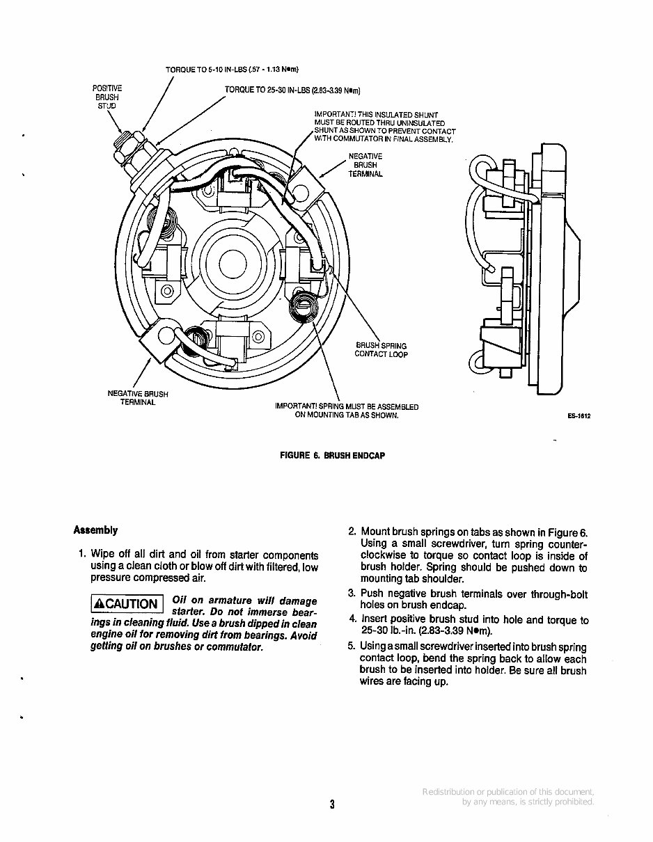
TORQUE TO 5-10 IN-LBS (.57 - 1.13 Nm) FIGURE 6. BRUSH ENDCAP Assembly 1. Wipe off all dirt and oil from starter components using a clean cloth or blow off dirt with filtered, low pressure compressed air. - 1 Oil on armature wi// damage starter. Do not immerse bear- ings in cleaning fluid. Use a brush dipped in clean engine oil for removing dirt from bearings. Avoid geffing oil on brushes or commutator. Es-1612 2. Mount brush springs on tabs as shown in Figure 6. Using a small screwdriver, turn spring counter- clockwise to torque so contact loop is inside of brush holder. Spring should be pushed down to mounting tab shoulder. 3. Push negative brush terminals over through-bolt holes on brush endcap. 4. Insert positive brush stud into hole and torque to 25-30 Ib.-in. (2.83-3.39 Nom). 5. Usingasmall screwdriver insertedinto brush spring contact loop, bend the spring back to allow each brush to be inserted into holder. Be sure all brush wires are facing up. 3
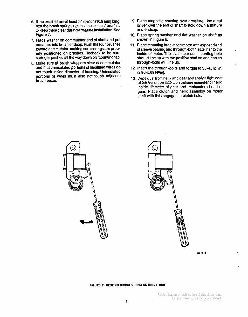
6. If the brushesareat least 0.430 inch (10.9 mm) long, rest the brush springs against the sides of brushes to keep them clear during armature installation. See Figure 7. 7. Place washer on commutator end of shaft and put armature into brush endcap. Push the four brushes toward commutator, making sure springs are prop- erly positioned on brushes. Recheck to be sure spring is pushed all the way down on mountingtab. 8. Make sure all brush wires are clear of commutator and that uninsulated portions of insulated wires do not touch inside diameter of housing. Uninsulated portions of wires must also not touch adjacent brush boxes. 9. Place magnetic housing over armature. Use a nut driver over the end of shaft to hold down armature and endcap. 10. Place spring washer and flat washer on shaft as shown in Figure 8. 11. Place mounting bracket on motor with exposed end of sleeve bearing and through-bolt"lead-ins" to the inside of motor. The "flat" near one mounting hole should line up with the positive stud on end cap so through-bolts will line up. , 12. Insert the through-bolts and torque to 35-45 Ib. in. (3.96-5.09 Nam). 13. Wipedustfrom helix and gearand applya light coat of GE Versilube 322-L on outside diameter of helix, inside diameter of gear and unchamfered end of gear. Place clutch and helix assembly on motor shaft with flats engaged in clutch hole. ES1611 FIGURE 7. RESTING BRUSH SPRING ON BRUSH SIDE 4
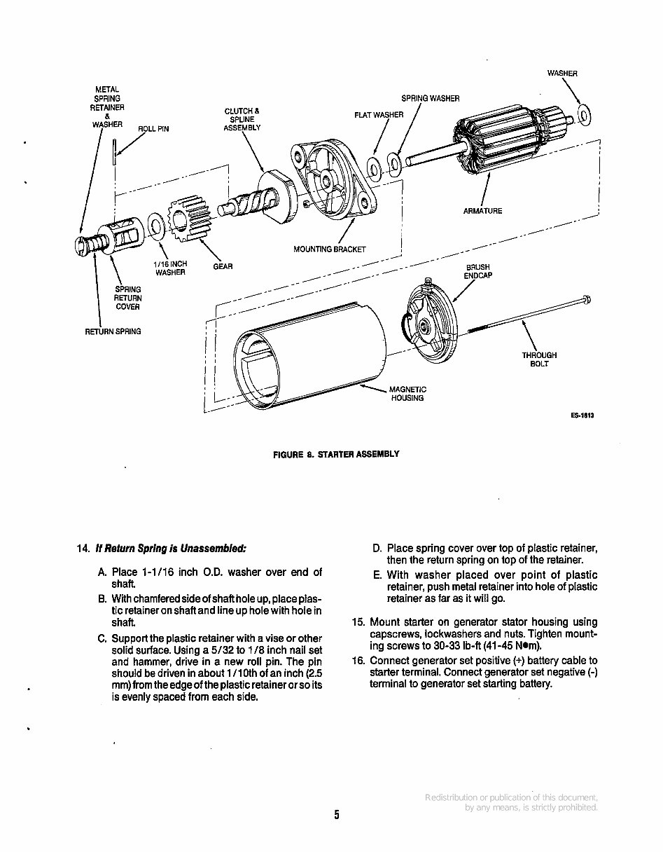
WASHER METAL SPRING SPRING WASHFR \ RETAINER & 1 I16 INCH WASHER 1 !,URN SPRING COVER RETURN SPRING \ MOUNTING EMCKET I ~ /-- FIGURE 8. STARTER ASSEMBLY 14. H Refurn Spring is Unassembled: A. Place 1-1/16 inch O.D. washer over end of shaft B. With chamfered side of shaft hole up, place plas- tic retainer on shaft and line up hole with hole in shaft. C. Support the plastic retainer with a vise or other solid surface. Using a 5/32 to 1 /8 inch nail set and hammer, drive in a new roll pin. The pin should be driven in about 1 /loth of an inch (2.5 mm) from the edge of the plastic retaineror so its is evenly spaced from each side. D. Place spring cover over top of plastic retainer, then the return spring on top of the retainer. E. With washer placed over point of plastic retainer, push metal retainer into hole of plastic retainer as far as it will go. 15. Mount starter on generator stator housing using capscrews, lockwashers and nuts. Tighten mount- ing screws to 30-33 Ib-ft (41 -45 Nom). 16. Connect generator set positive (+) battery cable to starter terminal. Connect generator set negative (-) terminal to generator set starting battery. 5
Supplement 940-1042 Date: 11-86 Insert with - Ti NHE-NHEL Service Manual Number: 940-0502 PURPOSE This supplement reflects the following manual updates: Page 1 (for units equipped with a Nikki carburetor) - New throttle stop, mixture adjustment, and float setting; in refer- ence to like information found on pages 6-13 to 6-16.
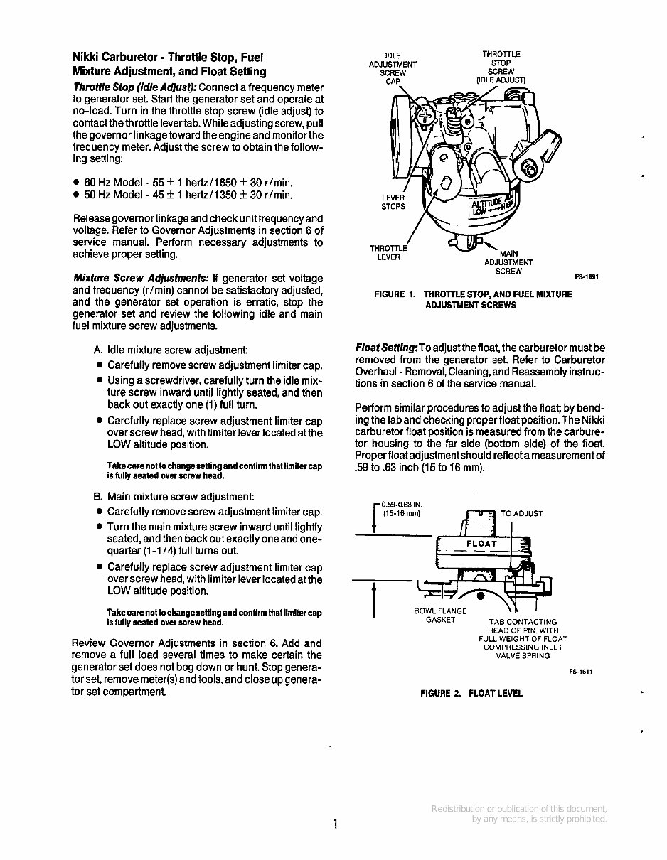
Nikki Carburetor - Throttle Stop, Fuel Mixture Adjustment, and Float Setting Throtlle Stop (/d/eAdjust): Connect a frequency meter to generator set. Start the generator set and operate at no-load. Turn in the throttle stop screw (idle adjust) to contactthe throttle levertab. While adjustingscrew, pull the governor linkagetoward the engine and monitor the frequency meter. Adjust the screw to obtain the follow- ing setting: 0 60 Hz Model - 55 f 1 hertz/1650 * 30 r/min. 50 Hz Model - 45 f 1 hertz/1350 k 30 r/min. Releasegovernor linkageand check unit frequency and voltage. Refer to Governor Adjustments in section 6 of service manual. Perform necessary adjustments to achieve proper setting. Mixture Screw Adjustments: If generator set voltage and frequency (rimin) cannot be satisfactory adjusted, and the generator set operation is erratic, stop the generator set and review the following idle and main fuel mixture screw adjustments. A. 0 0 0 B. 0 0 0 Idle mixture screw adjustment: Carefully remove screw adjustment limiter cap. Using a screwdriver, carefully turn the idle mix- ture screw inward until lightly seated, and then back out exactly one (1) full turn. Carefully replace screw adjustment limiter cap over screw head, with limiter lever located at the LOW altitude position. Takecarenottochangesettingandconfirm that limitercap is fully seated over screw head. Main mixture screw adjustment: Carefully remove screw adjustment limiter cap. Turn the main mixture screw inward until lightly seated, and then back out exactly one and one- quarter (1-1 /4) full turns out. Carefully replace screw adjustment limiter cap over screw head, with limiter lever located at the LOW altitude position. Take care not to changesetting and confirm that limitercap is fully seated over screw head. Review Governor Adjustments in section 6. Add and remove a full load several times to make certain the generator set does not bog down or hunt. Stop genera- tor set, remove meter(s)and tools, and close up genera- tor set compartment. IDLE THROTTLE ADJUSTMENT STOP SCREW SCREW CAP (IDLE ADJUSI) ADJUSTMENT SCREW LEVER FIGURE 1. THROTTLE STOP, AND FUEL MIXTURE ADJUSTMENT SCREWS FS-1691 F/oatSeffing:To adjustthefloat, the carburetor must be removed from the generator set. Refer to Carburetor Overhaul - Removal,Cleaning, and Reassemblyinstruc- tions in section 6 of the service manual. Perform similar procedures to adjust the float; by bend- ing the tab and checking properfloat position. The Nikki carburetor float position is measured from the carbure- tor housing to the far side (bottom side) of the float. Properfloat adjustment should reflecta measurementof .59 to .63 inch (15 to 16 mm). 059-0.63 IN. r (15-16 rnrn) luw TOADJUST t t BOWL FLANGE GASKET TAB CONTACTING HEAD OF PIN. WITH FULL WEIGHT OF FLOAT COMPRESSING INLET VALVE SPRING I FS-1611 FIGURE 2. FLOATLEVEL 1
The Onan Cummins NHE, NHEL Series Generators Service Repair Manual is a comprehensive workshop guide offering detailed servicing instructions designed for professional mechanics and DIY repair enthusiasts alike. This guide provides complete information on repair, servicing, preventative maintenance, and troubleshooting procedures for Onan Cummins Generators.
Featuring step-by-step instructions, detailed illustrations, exploded diagrams, drawings, and photos, it covers:
Major engine service
Engine sensors and governor actuator
Exhaust manifold and fuel system
Starter, battery charging alternator, and generator testing
Disassembly, reassembly, and generator reconnection
Line circuit breakers and safety precautions
Control panel operation and engine oil recommendations
Engine coolant, periodic maintenance, and generator set control
DC circuit breaker, engine oil pressure sender, coolant temperature sender, and starter relay
Specifications and wiring diagrams
This indispensable guide is formatted for easy navigation, allowing quick reference to service repair procedures, ensuring your generator remains in proper working condition. The manual is designed to be printed for hands-on use whenever needed.
Pages: 104
Printable: Yes
Language: English
If you are looking to master generator maintenance and repair, this manual serves as the only reference you need for your Onan Cummins NHE, NHEL Series Generators.
Recently Viewed
5,521,897Happy Clients
2,594,462eManuals
1,120,453Trusted Sellers
15Years in Business
Price:
Actual Price:
Onan NHE, NHEL Series Service Manual Cummins Onan Generator Repair Book 940-0502