

Canon A-1 A1 Camera Service Repair Manual
What's Included?
Fast Download Speeds
Offline Viewing
Access Contents & Bookmarks
Full Search Facility
Print one or all pages of your manual
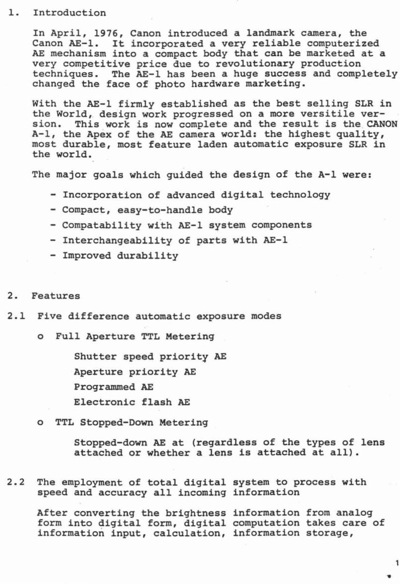
1. Introduction
In April, 1976, Canon introduced a landmark camera, the
Canon AE-l. It incorporated a very reliable computerized
AE mechanism into a compact body that can be marketed at a
very competitive price due to revolutionary production
techniques. The AE-l has been a huge success and completely
changed the face of photo hardware marketing.
With the AE-l firmly established as the best selling SLR in
the World, design work progressed on a more versitile ver-
sion. This work is now complete and the result is the CANON
A-l, the Apex of the AE camera world: the highest quality,
most durable, most feature laden automatic exposure SLR in
the world.
The major goals which guided the design of the A-l were:
- Incorporation of advanced digital technology
- Compact, easy-to-handle body
- Compatability with AE-l system components
- Interchangeability of parts with AE-l
- Improved durability
2. Features
2.1 Five difference automatic exposure modes
o Full Aperture TTL Metering
Shutter speed priority AE
Aperture priority AE
Programmed AE
Electronic flash AE
o TTL Stopped-Down Metering
Stopped-down AE at (regardless of the types of lens
attached or whether a lens is attached at all).
2.2 The employment of total digital system to process with
speed and accuracy all incoming information
After converting the brightness information from analog
form into digital form, digital computation takes care of
information input, calculation, information storage,
1
•
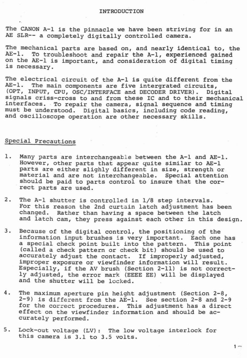
INTRODUCTION
The CANON A-l is the pinnacle we have been striving for in an
AE SLR-- a completely digitally controlled camera.
The mechanical parts are based on, and nearly identical to, the
AE-l. To troubleshoot and repair the A-l, experienced gained
on the AE-l is important, and consideration of digital timing
is necessary.
The electrical circuit of the A-l is quite different from the
AE-l. The main components are five intergrated circuits,
(OPT, INPUT, CPU, OSC / INTERFACE and DECODER DRIVER). Digital
signals criss-cross to and from these Ie and to their mechanical
interfaces . . To repair the camera, signal sequence and timing
must be understood. Digital basics, including code reading,
and oscilloscope operation are other necessary skills.
Special Precautions
1. Many parts are interchangeab le between the A-l and AE-l.
However, other parts that appear quite similar to AE-l
parts are either slighly different in size, strength or
material and are not interchange a ble. Special attention
should be paid to parts control to insure that the cor-
rect parts are used.
2. The A-l shutt er is controlle d in 1/8 step intervals .
For this reas on the 2nd curt a in latch adjustment has been
changed. Rather than having a space between the latch
and latch cam, they press against each other in this design.
3. Because of the digital control, the positioning of the
information in put brushes is very important . Each one has
a special check point built into the pattern . This point
(called a check pattern or check bit) should be used to
accurately adjust the contact. If improperly adjusted,
improper exposure or viewfinder information will result.
Especially, if the AV brush (Section 2-11) is not correct-
ly adjusted, the error mark (EEEE EE) will be displayed
and the shutter will be lock ed.
4. The maximum aperture pin height adjustment (Section 2-8,
2-9) is di ff er ent from the AE-l. See section 2-8 and 2-9
for the co rre ct procedures. This adjustment has a direct
effect on the viewfinder information and should be ac-
curately performed.
5. Lock-out volta ge (LV): The low voltage interlock for
this camera is 3.1 to 3.5 volts.
1 -
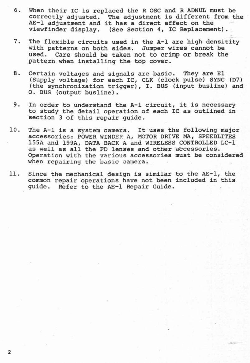
6. When their IC is replaced the R OSC and R ADNUL must be
correctly adjusted. The adjustment is different from the
AE-l adjustment and it has a direct effect on the
viewfinder display . (See Section 4, IC Replacement) .
7. The flexible circuits used in the A-I are high densitity
with patterns on both sides. Jumper wires cannot be
used. Care should be taken not to crimp or break the
pattern when installing the top cover.
S. Certain voltages and signals are basic . They are El
(Supply voltage) for each IC, CLK (clock pulse) SYNC (07)
(the synchronization trigger), I. BUS (input busline) and
O. BUS (output busline).
9. In order to understand the A-I circuit, it is necessary
to stud y the detail operation of each IC as outlined in
section 3 of this repair guide.
10 . The A-I is a system camera . It uses the following major
accessories: POWER WIND ER A, MOTOR DRIVE MA, SPEEDLITES
l55A and 199A, DATA BACK A and WIRELESS CONTROLLED LC-l
as well as all the FD lenses and other abcessories .
Oper a tion with the various accessories must be considered
whe n repairing the b asi c camera.
11 . Since the mechanical design is similar to the AE-l, the
common repair operations ha ve not been included in this
guide . Refer to the AE-l Repair Guide .
2
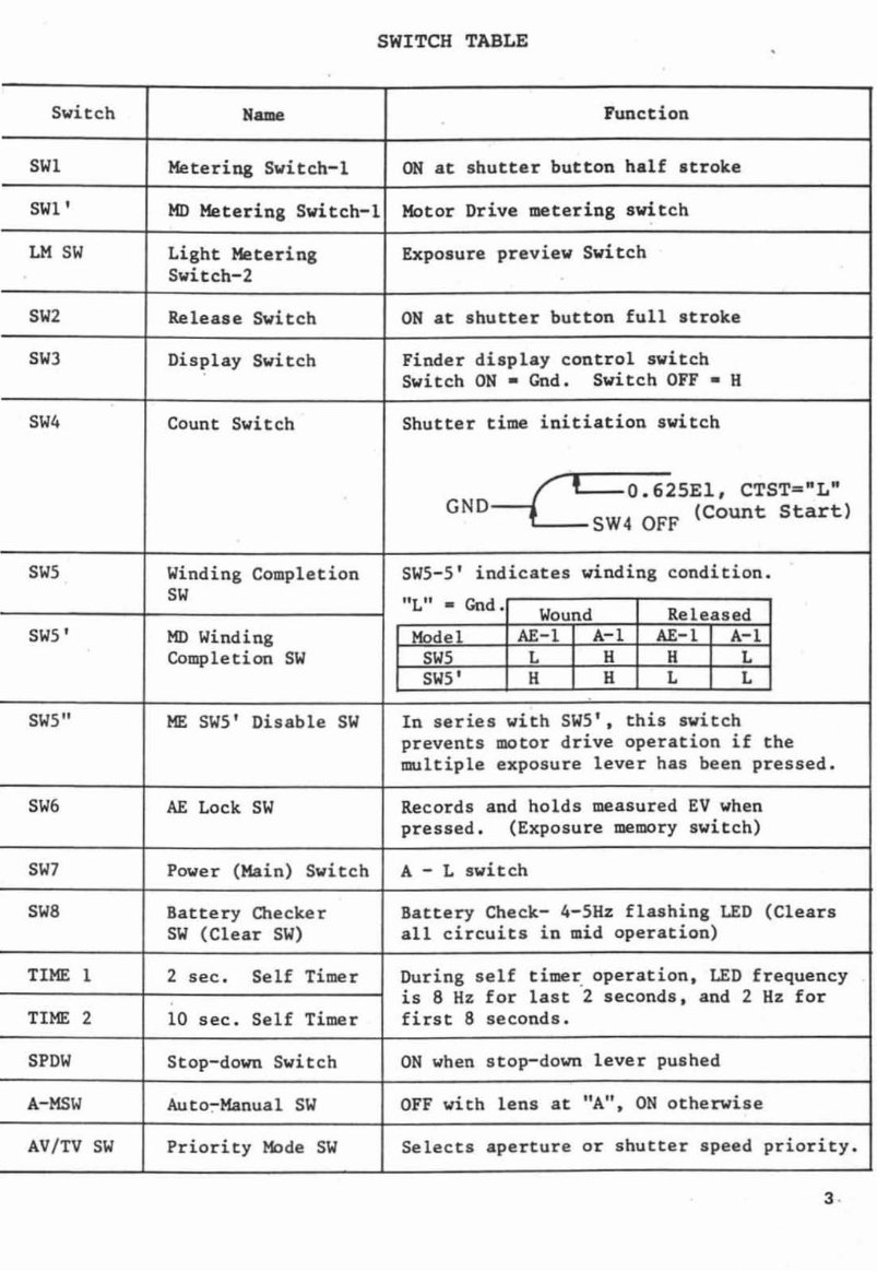
SWITCH TABLE
Switch
Name Function
SWl Metering Switch-L ON at shutter button half strok.e
SWl'
MD Metering Switch-l Motor Drive metering switch
LM SW Light Metering Exposure preview Switch
Switch-2
SW2 Release Switch ON at shutter button full stroke
SW3 Display Switch Finder display control switch
Switch ON - Gnd. Switch OFF . H
SW4 Count Switch Shutter time initiation switch
r==:O.625El, CTST="L"
GND _ SW4 OFF (Count Start)
SWS Winding CompLetion SWS-5' indicates winding c ondition.
SW
"L" • Cod .
Wound Rel eased
SW5' lID Winding Model AE-l A-l AE-l A-l
Completion SW SWS L H H L
SW5' H H L L
SWS
II
ME SW5' Di sable SW In series with SW5' t this switch
prevents motor drive operation if the
multiple exposure lever has been pressed.
SW6 AE Lock SW Records and holds measured EV when
pressed. (Exposure memory switch)
SW7 Power (Kain) Switch A - L switch
SW8 Battery Checker Battery Check- 4-5Hz flashing LED (Clears
SW (Clear SW) all circuits in mid operation)
TIME 1 2 sec . S eU Timer During self timer: operation. LED frequency
is 8 Hz for last 2 seconds, and 2 Hz for
TIME 2 10 sec. SeU Timer first 8 seconds.
spew
Stop-down Switch ON when sto p-down lever pushed
A-M$W Auto:-Manual SW OFF with lens at "A", ON otherwise
AV/TV SW Priority Mode SW Selects aperture or shutter speed priority.
3·
You're Reading a Preview
What's Included?
Fast Download Speeds
Offline Viewing
Access Contents & Bookmarks
Full Search Facility
Print one or all pages of your manual
$27.99
Viewed 61 Times Today


Secure transaction
What's Included?
Fast Download Speeds
Offline Viewing
Access Contents & Bookmarks
Full Search Facility
Print one or all pages of your manual
$27.99
This is a service repair manual for the Canon A-1 (A 1) camera. It contains illustrated pictures and step-by-step instructions used by Canon technicians. This manual is useful for both professional mechanics and DIY enthusiasts, enabling easy camera repair and saving on workshop costs.
- Disassembly and Part Replacement
- Schematic and Circuit Diagrams
- Repair Hints
- Troubleshooting
- Service Information
- Technical Explanation
- Maintenance Tools
This manual is available for instant access without any shipping costs. It guarantees satisfaction with its comprehensive content.


