ENGINES 4.3L V6 MODEL IDENTIFICATION MODEL IDENTIFICATION ENGINE IDENTIFICATION Engine can be identified by eighth character of Vehicle Identification Number (VIN). VIN is stamped on a metal tag on top left end of instrument panel, near windshield. See ENGINE IDENTIFICATION table. Engine can also be identified by engine identification (ID) number. Number is stamped on front of cylinder block, immediately forward of right cylinder head or on left side of cylinder block, on engine-to-transmission mating flange. ENGINE IDENTIFICATION ADJUSTMENTS VALVE CLEARANCE ADJUSTMENT (VIN W) No valve adjustment is necessary. This engine has screw-in rocker arm studs with positive stop shoulders. Model Body Code Astro & Safari; AWD, 2WD L, M Blazer, Jimmy, Sonoma & S10 Pickup; 2WD,4WD S, T Bravada, Syclone & Typhoon T Parcel/Delivery Commercial Van Motorhome P Pickup; 2WD,4WD C, K Van, Rally Van, Vandura G NOTE: Information applies to both 1991 and 1992 Syclone and Typhoon. NOTE: For engine repair procedures not covered in this article, see ENGINE OVERHAUL PROCEDURES - GENERAL INFORMATION article in the GENERAL INFORMATION section. Application Option Code Engine Code (1) 4.3L V6 CPI L35 W TBI LB4 Z PFI Turbo LB4 Z (1) Engine code is eighth character of Vehicle Identification Number (VIN).
When the valve train requires service, you simply tighten the rocker arm nuts to 20 ft. lbs. (27 N.m). VALVE CLEARANCE ADJUSTMENT (VIN Z) This engine can be equipped with two different rocker arm stud configurations that require different valve lash procedures. If your engine has screw-in rocker arm studs with positive stop shoulders, no valve adjustment is necessary. When the valve train requires service, you simply tighten the rocker arm nuts to 20 ft. lbs. (27 N.m) If your engine has pressed-in rocker arm studs, you must follow the valve adjustment procedure outlined below. 1. Rotate engine until No. 1 piston is on TDC of compression stroke. Loosen rocker arm adjusting nut until lash is present. 2. Tighten adjusting nut until lash is removed. Tighten adjusting nut one full turn. Adjust remaining valves (for piston at TDC) as listed in the VALVE CLEARANCE ADJUSTMENT table. 3. Rotate crankshaft 360 degrees to bring No. 4 piston to TDC of compression stroke. Adjust remaining valves. See the VALVE CLEARANCE ADJUSTMENT table. VALVE CLEARANCE ADJUSTMENT TROUBLE SHOOTING To trouble shoot engine mechanical problems, see ENGINE MECHANICAL in BASIC TROUBLE SHOOTING article in GENERAL INFORMATION. REMOVAL & INSTALLATION FUEL PRESSURE RELEASE Disconnect battery terminals. Loosen fuel tank cap to relieve tank pressure. Internal constant bleed feature in injection unit relieves fuel system pressure when ignition switch is turned off. No further pressure relief is Piston At TDC Intake Exhaust No. 1 No. 1, 2 & 3 No. 1, 5 & 6 No. 4 No. 4, 5 & 6 No. 2, 3 & 4 CAUTION: When battery is disconnected, vehicle computer and memory systems may lose memory data. Driveability problems may exist until computer systems have completed a relearn cycle. See COMPUTER RELEARN PROCEDURES article in the GENERAL INFORMATION section before disconnecting battery. NOTE: For reassembly reference, label all electrical connectors, vacuum hoses and fuel lines before removal. Also place mating marks on engine hood and other major assemblies before removal.
required. ENGINE Removal & Installation (Astro & Safari) 1. Release fuel system pressure. See FUEL PRESSURE RELEASE under REMOVAL & INSTALLATION. Disconnect battery. Drain cooling system. Raise and support vehicle. 2. Disconnect exhaust pipes from manifolds. Remove flywheel cover, torque converter bolts (A/T), starter and oil filter. Disconnect engine wiring harness from transmission and frame. 3. Disconnect fuel lines from frame. Disconnect transmission fluid lines and engine oil cooler lines from radiator. Remove lower fan shroud bolts. Remove motor mount through-bolts. Lower vehicle. 4. Remove headlight bezels and grille. Remove lower radiator close-out panel, radiator support braces and radiator cross brace. Remove hood latch mechanism. Discharge A/C system (if equipped) using approved refrigerant recovery/recycling equipment. Remove master cylinder, upper fan shroud, upper radiator core support and radiator. 5. Remove radiator filler panels. Remove engine cover. Disconnect A/C hose from accumulator. Remove A/C compressor and bracket. Remove power steering pump. 6. Disconnect vacuum hoses as necessary. Disconnect engine wiring harness clips from firewall. Remove right kick panel. Disconnect engine wiring harness connector from ESC module. Push connector and harness through firewall. Remove distributor cap and A/C accumulator. Disconnect fuel line from injection unit. 7. Remove transmission dipstick tube. Disconnect heater hose from heater core. Remove horn. Support transmission. Support engine with adjustable jack. Remove bellhousing bolts. Lower engine from vehicle. 8. To install, reverse removal procedure. Fill crankcase and cooling system. Evacuate and charge A/C system. Removal & Installation (Bravada) 1. Release fuel system pressure. See FUEL PRESSURE RELEASE under REMOVAL & INSTALLATION. Disconnect battery. Remove hood. Raise and support vehicle. Drain cooling system and crankcase. 2. Disconnect exhaust pipes from manifolds. Disconnect drive shaft from front differential. Remove starter. Remove flywheel cover and torque converter bolts. Remove engine mount through-bolts. Remove oil filter adapter. 3. Remove strut rod. Remove bellhousing bolts. Disconnect transmission fluid cooler lines from clips. Lower vehicle. Remove air cleaner, upper fan shroud, accessory drive belt and fan/clutch assembly. 4. Remove A/C compressor with hoses attached and position aside (if equipped). Remove radiator. Disconnect power steering hoses from power steering pump. Disconnect fuel lines, electrical connectors, vacuum hoses, coolant hoses and control cables as necessary. 5. Remove alternator. Disconnect spark plug wires from distributor cap. Remove cap. Support transmission. CAUTION: Minimal clearance exists between oil pump pick-up tube and bottom of oil pan. DO NOT place jack under oil pan, crankshaft pulley or any sheet metal when lifting engine.
Remove bracket from oil cooler. Attach engine hoist. Remove engine. 6. To install, reverse removal procedure. Fill crankcase and cooling system. Bleed power steering fluid system. Removal & Installation ("C" & "K" Series) 1. Release fuel system pressure. See FUEL PRESSURE RELEASE under REMOVAL & INSTALLATION. Disconnect battery. Remove hood. Remove air cleaner, accessory drive belt, fan and water pump pulley. 2. Drain cooling system. Remove fan shroud and radiator. Disconnect heater hoses from engine. Disconnect fuel lines, electrical connectors, vacuum hoses, coolant hoses and control cables as necessary. Remove A/C compressor and power steering pump with hoses attached and position aside (if equipped). 3. Raise and support vehicle. Drain crankcase. Disconnect exhaust pipes from manifolds. Disconnect strut rods. Remove flywheel cover. Remove starter. Remove torque converter bolts (A/T). Lower vehicle. 4. Support transmission. Attach engine hoist. Remove bellhousing bolts. Remove front engine mount-to- frame bolts. Remove engine. To install, reverse removal procedure. Fill crankcase and cooling system. Evacuate and charge A/C system. Removal & Installation (Commercial Van) 1. Release fuel system pressure. See FUEL PRESSURE RELEASE under REMOVAL & INSTALLATION. Disconnect battery. Drain cooling system. Remove engine cover and floor panel sections. 2. Remove air cleaner, duct and exhaust heat stove pipe. Remove distributor cap and position aside. Disconnect all engine harness electrical connectors and position aside. Disconnect fuel lines from injection unit. Remove fuel line clamps from transmission and position fuel lines aside. 3. Disconnect ground strap from rear end of left cylinder head. Disconnect all transmission harness electrical connectors and position harness aside. Remove transmission shifter (if necessary). Remove upper radiator hose, all accessory drive belts, fan, fan pulley, fan shroud and lower radiator hose. 4. Remove engine oil filler tube. Remove clutch adjuster rod, return spring and pivot arm assembly (M/T). Disconnect exhaust pipes from manifolds. Disconnect battery cable from clamp on cylinder block. Disconnect drive shaft from transmission. Remove transmission mount. 5. Disconnect oil cooler lines from oil filter adapter and oil cooler line clamps from engine. Attach engine hoist. Remove engine mount through-bolts. Remove engine and transmission assembly through side door. To install, reverse removal procedure. Fill crankcase and cooling system. Removal & Installation ("G" Series) 1. Release fuel system pressure. See FUEL PRESSURE RELEASE under REMOVAL & INSTALLATION. Disconnect battery. Drain cooling system. Remove engine cover and air cleaner. Remove power steering fluid reservoir. 2. Remove upper fan shroud, fan, fan pulley, radiator and lower fan shroud. Discharge A/C system (if NOTE: On Commercial Van, engine and transmission are removed as an assembly through side door.
equipped) using approved refrigerant recovery/recycling equipment. Remove A/C condenser. Remove A/C compressor and brace. Remove alternator. Remove cruise control servo (if equipped). 3. Disconnect fuel lines, electrical connectors, vacuum hoses, coolant hoses and control cables as necessary. Remove injection unit. Remove distributor cap with wires attached. Remove diverter valve assembly and pipe. 4. Remove ignition coil and manifold absolute pressure sensor. Remove upper half of engine oil dipstick tube. Remove engine oil filler tube. Remove headlight bezels, grille and upper radiator support (sheet metal cross panel support). 5. Raise and support vehicle. Drain crankcase. Disconnect exhaust pipes from manifolds. Remove strut rods. Remove flywheel cover. Disconnect oil cooler lines from engine. Remove starter, torque converter bolts (A/T) and engine mount through-bolts. 6. Lower vehicle. Attach engine hoist. Remove bellhousing bolts. Support transmission. Remove engine. To install, reverse removal procedure. Fill crankcase and cooling system. Evacuate and charge A/C system. Removal & Installation ("S" Series) 1. Release fuel system pressure. See FUEL PRESSURE RELEASE under REMOVAL & INSTALLATION. Disconnect battery. Remove hood. Drain cooling system. 2. Disconnect upper radiator hose from radiator. Remove coolant overflow hose and upper fan shroud. Disconnect transmission fluid lines and engine oil cooler lines (if equipped). Remove radiator and fan. Disconnect heater hoses. Remove air cleaner. 3. Disconnect fuel lines, electrical connectors, vacuum hoses, coolant hoses and control cables as necessary. Remove distributor cap. Raise and support vehicle. Disconnect exhaust pipe from converter and manifolds. Remove strut rods and flywheel cover. 4. Remove torque converter bolts (A/T). Remove shield from rear of catalytic converter. Disconnect converter hanger from exhaust pipe. Remove 2 outer air dam bolts. Remove left body mount bolts, raise and support body and remove bellhousing bolts. Lower body. 5. Remove motor mount through-bolts. Lower vehicle. Remove A/C compressor and power steering pump with hoses attached and position aside (if equipped). Attach engine hoist. Support transmission. Remove engine. To install, reverse removal procedure. Fill crankcase and cooling system. Removal & Installation (Syclone & Typhoon) 1. Release fuel system pressure. See FUEL PRESSURE RELEASE under REMOVAL & INSTALLATION. Disconnect battery cables and remove battery. Remove hood from vehicle. 2. Remove air cleaner and duct, drain engine coolant radiator and charge air cooler radiator. Remove Turbocharger air inlet elbow, Upper fan shroud and Fan & Pulley nuts. Remove battery tray and vacuum tank. 3. Raise and suitably support vehicle. Remove front tires, wheels and wheelhouse panels. Disconnect muffler(s) and tailpipe from catalytic converter. Remove catalytic converter support bolts, turbocharger outlet pipe bracket and turbocharger outlet pipe nuts. Move outlet pipe and catalytic converter away from the turbocharger. 4. Disconnect electrical connector from charge air cooler radiator temperature sensor and radiator hoses. Remove charge air cooler radiator and exhaust crossover pipe. Lower vehicle. 5. Disconnect transmission cooler lines and upper & lower radiator hoses from radiator. Disconnect engine
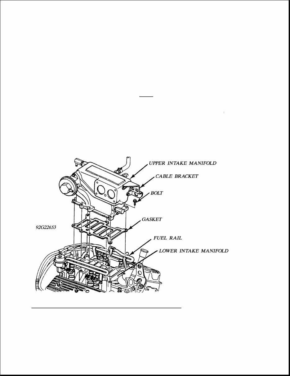
oil cooler lines and heater & overflow hoses from radiator. Remove radiator. 6. Disconnect oil pipes at filter adapter. Remove power steering pump hoses from steering gear. 7. Remove engine coolant reservoir and A/C compressor from bracket. Move aside. Disconnect charge air cooler clamps, ducts and hoses. Remove charge air cooler from supports. 8. Remove throttle body, throttle body gasket, bolts and cable bracket from upper intake manifold and move aside. 9. Disconnect heater hose from lower intake manifold, electrical connectors and hoses from upper intake manifold. Remove upper in take manifold. See Fig. 1 . Fig. 1: Upper Intake Manifold Removal (Syclone & Typhoon) Courtesy of GENERAL MOTORS 10. Disconnect fuel pipes from fuel rail. Disconnect electrical connectors and vacuum lines from engine. Raise and suitably support vehicle. 11. Disconnect rear drive shaft (Support Transmission). Remove transmission crossmember and mount.
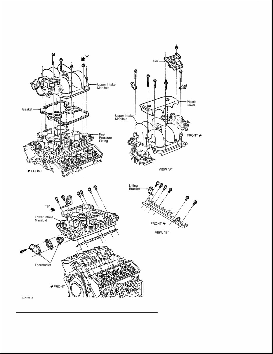
Disconnect front drive shaft and remove torque converter cover. Disconnect shift linkage from transmission. 12. Remove torque converter bolts. Remove fuel pipes from hoses near transfer case and fuel line bracket from transfer case. Disconnect fuel line, electrical clips and connectors from transmission and transfer case. Remove transfer case and gasket. Disconnect TV cable and transmission cooler lines from transmission. Remove torque converter housing bolts and transmission. Disconnect transmission cooler lines from oil pan. 13. Remove fuel line, oil line and electrical harness clips from cylinder heads. Disconnect starter motor electrical connections and remove starter motor. Remove mount through-bolts and nuts. Lower vehicle. 14. Disconnect electrical connections from oil pressure and knock sensors and ground strap. Install lifting device. Remove Engine. To install, reverse removal procedure. Fill crankcase, cooling system and charge air cooler system. Removal & Installation ("T" Series, Except Syclone & Typhoon) 1. Release fuel system pressure. See FUEL PRESSURE RELEASE under REMOVAL & INSTALLATION. Disconnect battery. Remove hood. Raise and support vehicle. 2. Loosen or remove body mount bolts. Raise and support body. Remove upper bellhousing bolts and front air dam end bolts. Lower body. Remove remaining bellhousing bolts. Remove No. 2 frame crossmember. Disconnect exhaust pipes from manifolds. 3. Disconnect catalytic converter hanger. Remove flywheel cover bolts. Disconnect front drive shaft from differential. Remove flywheel cover. Disconnect transmission cooler lines from engine clips. Remove motor mount bolts. 4. Remove torque converter bolts. Remove front splash shield and lower fan shroud bolts. Lower vehicle. Drain cooling system. Remove upper fan shroud. Disconnect radiator hoses from radiator. Disconnect oil filter pipe from remote oil filter. 5. Remove radiator, fan and air cleaner. Remove A/C compressor and power steering pump with hoses attached and position aside (if equipped). Disconnect fuel lines, electrical connectors, vacuum hoses, coolant hoses and control cables as necessary. 6. Support transmission. Attach engine hoist. Remove engine. To install, reverse removal procedure. Fill crankcase and cooling system. INTAKE MANIFOLD Removal (VIN W) 1. Release fuel system pressure. See FUEL PRESSURE RELEASE under REMOVAL & INSTALLATION. Disconnect battery. Drain cooling system. 2. Disconnect fuel lines, electrical connectors, vacuum hoses, coolant hoses and control cables as necessary. Remove upper intake manifold and gasket. See Fig. 2 . Remove alternator bracket, A/C compressor (with hoses attached) and cruise control servo as necessary. 3. Remove distributor cap. Mark distributor rotor in relation to distributor housing. Mark base of distributor housing in relation to lower intake manifold. Remove distributor. Remove electrical connectors, fuel rails and fuel injectors. Remove lower intake manifold bolts, lower intake manifold and gaskets.
Fig. 2: Exploded View Of Intake Manifold Assembly (VIN W) Courtesy of GENERAL MOTORS CORP.
Installation 1. Install gaskets on cylinder heads. Apply a 3/16" bead of RTV silicone sealant to front and rear lower intake manifold-to-cylinder block mounting surfaces. See Fig. 2 . Extend bead 1/2" beyond cylinder block-to-cylinder head junction. 2. Install lower intake manifold on cylinder block. Tighten bolts in sequence to specification. See Fig. 3 . Install fuel injectors, fuel rails and electrical connectors removed during disassembly. 3. Install distributor, A/C compressor and cruise control servo (if equipped). Install upper intake manifold gasket. Install upper intake manifold and bolts. Tighten retaining bolts in sequence to specification. See Fig. 4 . See TORQUE SPECIFICATIONS . 4. To complete installation, reverse removal procedure. Fill cooling system.
If you are in need of a repair manual for your 1992 GMC Typhoon, look no further. Our accessible repair manual software is the perfect resource for both professional mechanics and DIY enthusiasts. In the past, traditional service manuals in book format were costly and inconvenient. Our repair manual software provides the same valuable information at a more affordable price and in a more convenient digital format.
Whether you are looking to fix the brakes, replace suspension components, address engine issues, or perform standard maintenance, this manual has you covered. It includes comprehensive service information for the brakes, engine, suspension, steering, drivetrain, electrical systems, heating, air conditioning, and more.
By utilizing this repair manual software, you can save a significant amount of money on vehicle repairs. Professional mechanics often charge high fees for their services, making a DIY approach a cost-effective alternative. The manual is designed for ease of use and is compatible with Windows, Mac computers, smartphones, and tablets.