FC7200 Flail Chopper PARTS MANUAL Replaces 902378 Form No. 908009
Introduction When ordering service parts, specify the correct part number, full description, quantity required, the unit model number and serial number. The model and serial number for this unit are stamped on a plate located on the left rear of the Main Frame adjacent to the Lift Control Crank. “Right” and “Left” are determined from a position standing at the rear of the unit facing the direction of travel. From this position, the Transmission and Drive are on the “Left” side. GEHL Company reserves the right to make changes or improvements in the design or construction of any part of the unit without incurring the obligation to install such changes on any previously delivered units. NOTE: On original tire replacement, Company policy prohibits the sale of replacement tires for all GEHL machinery. Replacement Wheel Sets are available and tire size information is called out with the Wheel Sets to facilitate replacement tire selection. ALL REPLACEMENT TIRES MUST BE PURCHASED LOCALLY. Refer to the abbreviations table located on this page for the various fastener descriptions. Standard attaching hardware torque values are also provided on the inside back cover. In the exploded view parts list, Reference Numbers may have additional information following the Reference Number. A Tear Drop symbol will indicate an application of a “wet” product such as oil, and the number inside the Tear Drop will correspond to the description in the Parts List. Also, a number inside of a hexagon will be the torque value required, in foot pounds, on the associated Reference Number. Items shown in the parts list that do not have Reference Numbers are shown for reference purposes only and are NOT available for purchase. Unless otherwise specified, all Cap Screws or Bolts are Grade 5, cadmium or zinc plated; Hexagon Nuts for Grade 5 Screws or Bolts are Grade B; Hexagon Nuts for other Screws or Bolts are Grade A. NOTE: The following abbreviations may be used herein: AR – As Required ASSD – Assembled ASSY – Assembly CB – Carriage Bolt CP – Cotter Pin CS – Cap Screw (Hexagon Head) CTR – Center DEG – Degree DIA – Diameter FCS – Flanged Cap Screw FHMS – Flat Head Machine Screw FLN – Flanged Lock Nut (Hexagon) FLS – Flanged Lock Screw (Hexagon) FW – Flat Washer GA – Gauge GR – Grade HD – Hard or Head HN – Hex Nut INCL – Includes IT-LW – Internal Tooth (Lock Washer) LT – Left LN – Lock Nut LW – Lock Washer JN – Jam Nut M – Metric MM/mm – Millimeter NF – National Fine NILN – Nylon Insert Lock Nut PB – Plow Bolt PTO – Power Take Off PTHMS – Phillips Truss Head Machine Screw RHMS – Round Head Machine Screw RPM – Revolutions Per Minute RT – Right SERR – Serrated SHCS – Socket Head Cap Screw SHSS – Socket Head Set Screw SN – Serial Number or Slotted Nut SQ – Square SQHSS – Square Head Set Screw T – Tooth or Teeth TFS – Thread Forming Screw THRD – Thread WLDMT – Weldment # – Number () – (Quantity Used Here) – Torque Required in foot pounds – Indicates a Fluid Application
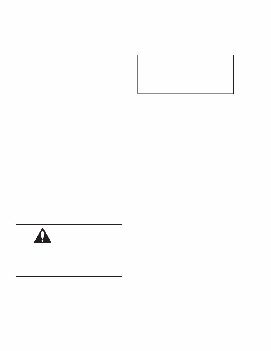
908009/AP1098 2 Printed in U.S.A. CHAPTER 1 DECAL LOCATIONS GENERAL INFORMATION Decal locations information is provided to assist in the proper selection and application of new decals, in the event the original decals become damaged or the machine is repainted. Refer to the listing for the illustration reference number, part number, description and quantity of each decal provided in the kit. Refer to the appropriate illustrations for replacement locations. NOTE: Refer to the SAFETY chapter of the Operator’s Manual for the specific information provided on all of the various safety decals furnished in the decal kit(s). To insure proper selection for correct replacement decals, compare all of the various close-up location photographs to your machine BEFORE starting to refinish the unit. Then circle each pictured decal applicable to your machine and check off its part number in the listing. After you have verified all the decals needed for replacement, set aside unneeded decals for disposal. NEW DECAL APPLICATION Surfaces MUST be free from dirt, dust, grease and other foreign material before applying the new decal. To apply a solid-formed decal, remove the smaller portion of the decal backing paper and apply this part of the exposed adhesive backing to the clean surface while maintaining proper position and alignment. Slowly peel off the other portion of the backing paper while applying hand pressure to smooth out the decal surface. CAUTION ALWAYS observe safety precautions shown on decals. If decals become damaged, or if the unit is repainted, replace the decals. If repainting, BE SURE that ALL decals from the Kit(s) that apply to your machine are affixed to your unit. PAINT NOTICE Use this list to order paint for refinishing: 901225 One Gal. Blaze 901226 One Gal. Maize 610239 6 (12 oz. Spray Cans) Blaze 610240 6 (12 oz. Spray Cans) Maize NOTE: Discard Decals NOT required for this machine. Always order Decals by set number. DO NOT order Decals separately. The Decal Set Number for the FC7200 is 093467. The set includes the following: Ref. Part No. No. Description & Quantity 1. 053373 Decal - Drive Belts 2. 060589 Decal - Lubricating Instruction 3. 060988 Decal - Transmission Oil Level 4. 061204 GEHL 29 x 6 5. 061205 GEHL 35 x 7 6. 065827 Decal - Shear Bolts 7. 068162 7200 (Vertical) 8. 089281 7200 (Horizontal) 9. 091444 DANGER - Rotating Component 10. 093020 Lubrication Symbol 11. 093365 WARNING - Close or Replace Guard (2 Places) 12. 093367 WARNING - Owner’s Responsibility & Read Manual 13. 093373 WARNING - General Safety 14. 093378 DANGER - Rotating Components (3 Places) 15. 093465 WARNING - 1000 RPM Operation ONLY 093466 WARNING - 540 RPM Operation ONLY (Not Shown) 16. 143007* DANGER – Shield Missing * Not Included in Decal Kit.
This is the complete parts manual for the GEHL FC7200 Flail Chopper.
It contains all the information needed to properly replace parts on the GEHL FC7200 Flail Chopper. The manual is filled with illustrations, part numbers, step-by-step instructions, and highly detailed exploded pictures and diagrams to guide through the required job efficiently. It's a valuable resource for both professional mechanics and DIY enthusiasts.
The table of contents includes:
Introduction
Decal Locations
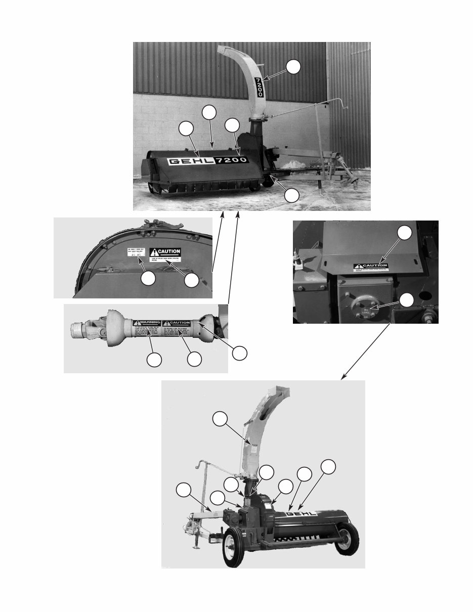
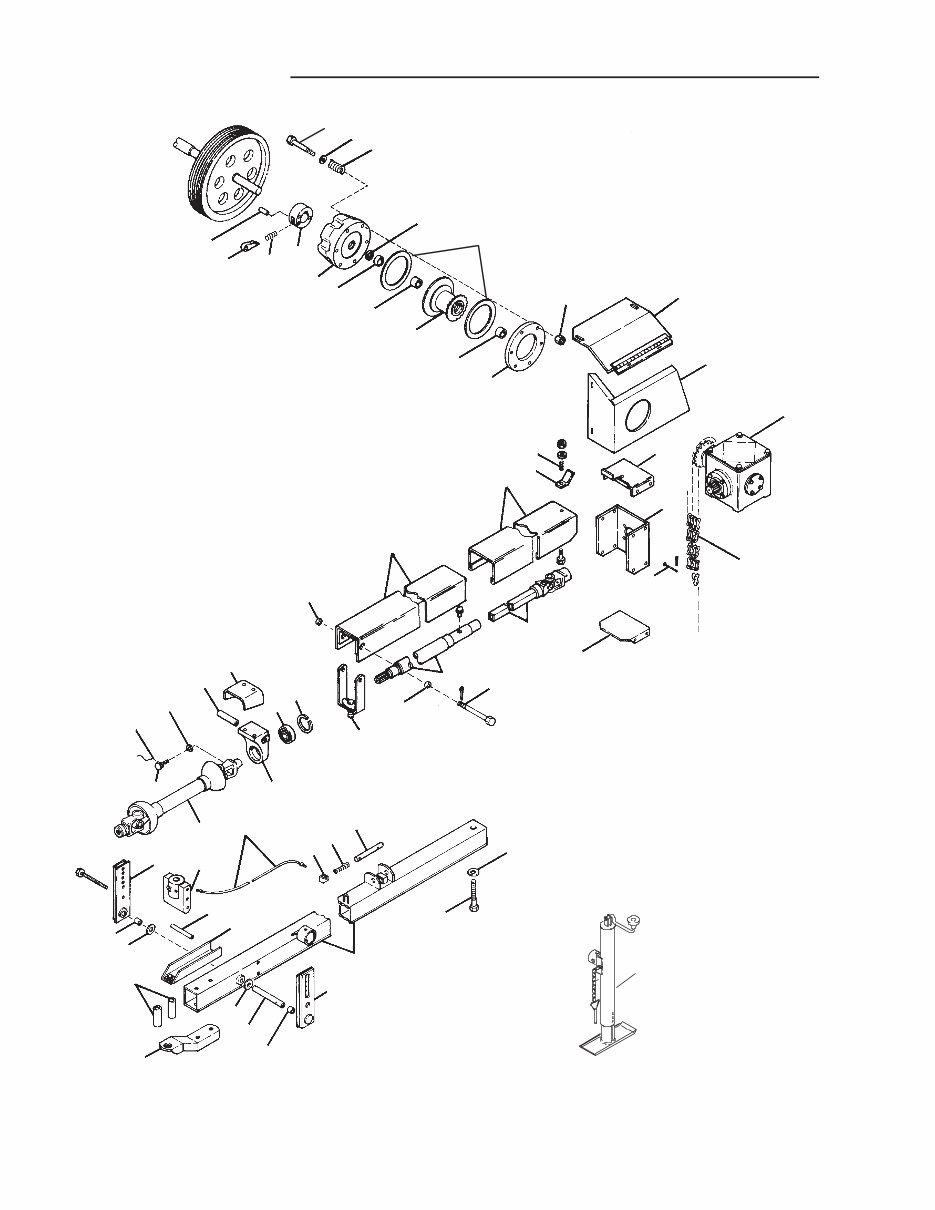
Frame, Axles & Lift Control
PTO & Drive
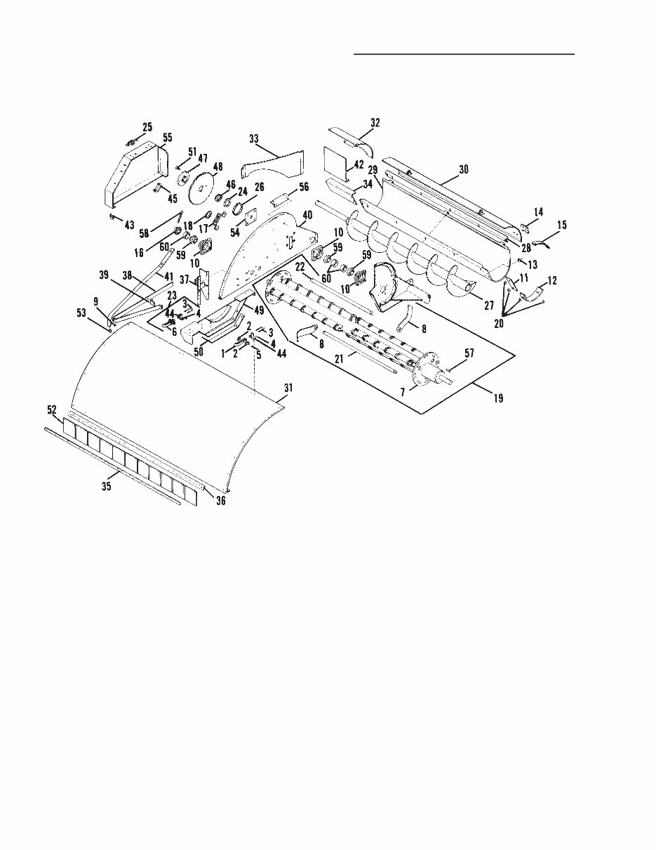
Cylinder, Conveyor & Drives
Blower-Cutter & Drive
Deflector, Cap & Controls
Transmissions
Hitchjacks
Universal Drives
Options & Accessories
Deflector Brace Kit
Trough Deflector Kit
Conveyor Cover Kit
3-Knife & Fan Kit
PTO High Pedestal Kit
1-Ft. Vertical Extension
3-Ft. Horizontal Extension
Hydraulic Lift Kit
Hydraulic Cylinder & Hose Kit
Service Kits
Alphabetical Index
Numerical Index
Standard Hardware Torque Specifications
Model Specification: GEHL FC7200 Flail Chopper
Language: English
File Format: PDF
Requirements: Adobe Reader
Compatibility: All Versions of Windows & Mac, APP ISO, Iphone, Ipad, Android etc...
This quality manual is 100% complete and intact, with no missing/corrupt pages or sections.
The file is bookmarked and searchable, making it easy to find what you need.
Detailed illustrations, exploded diagrams, drawings, and photos guide you through every service repair procedure.
This manual can be viewed on any computer, zoomed, and printed. It comes in PDF format, which is compatible with all PC-based Windows operating systems and Mac. It can be saved to your hard drive and burned to CD-ROM.
Instant access means there will be no shipping costs or waiting for a paper or CD manual to arrive in the mail. You will receive this manual today via instant download on completion of payment via our secure payment processor.
We accept all major credit/debit cards and PayPal.